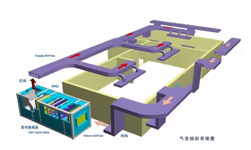
A Combination Air Handling Unit (AHU) is a multi-functional device that integrates air mixing, filtration, cooling, heating, humidification, dehumidification, noise reduction, air purification, and air supply. Proper selection of an AHU ensures optimal performance in HVAC systems for commercial and industrial applications.
This guide will cover the selection process, calculation methods, and key parameters for choosing the right AHU.
1. Key Factors in AHU Selection
The AHU selection process primarily involves determining the following parameters:
✔ Airflow (Supply Air Volume, m³/h or CFM)
✔ Cooling and Heating Capacity (kW or BTU/h)
✔ Pre-coil and Post-coil Air Conditions (temperature, humidity)
✔ Return Air System Type (single-pass or two-pass return air)
Types of Return Air Systems:
- Single-Pass Return Air System: The AHU directly processes return air and fresh air.
- Two-Pass Return Air System: The air undergoes two stages of conditioning before being supplied to the space.
2. Preparation Before Calculation
Before calculating the AHU parameters, the following preparatory work is necessary:
2.1 Psychrometric Chart (Enthalpy-Humidity Diagram)
- A psychrometric chart helps visualize temperature, humidity, enthalpy, and dew point changes during the air treatment process.
- It can be generated using HVAC design software.
2.2 Required Input Parameters
To accurately size an AHU, gather the following data:
✔ Indoor Design Parameters: Temperature and relative humidity requirements.
✔ Outdoor Design Parameters: Location-specific dry-bulb and wet-bulb temperatures.
✔ Cooling Load & Latent Load: Internal cooling and dehumidification requirements.
✔ Supply Air Temperature Differential: Temperature difference between supply and return air.
✔ Fresh Air Requirements: Percentage or absolute volume of fresh air needed.
✔ Supply & Return Duct Heat Gain: Temperature increase during air distribution.
✔ Dew Point Relative Humidity: Typically set between 90% – 95% for air conditioning calculations.
3. Input Parameters and Calculations
3.1 Indoor Condition Parameters
Indoor temperature and humidity values depend on the application. Example for an office:
- Dry-bulb temperature: 25°C
- Relative humidity: 50%
3.2 Cooling & Humidity Load Calculation
- Cooling load (kW or BTU/h) → Represents the heat load to be removed.
- Humidity load (kg/h) → Represents the amount of moisture to be removed.
- Can be calculated using HVAC load calculation software.
3.3 Outdoor Condition Parameters
Outdoor temperature and humidity vary by location. Example for Beijing, China:
- Dry-bulb temperature: 33.5°C
- Wet-bulb temperature: 26.4°C
3.4 Supply Air Temperature Differential
- The supply air temperature must ensure a comfortable indoor environment while minimizing airflow volume for cost savings.
- Dew point-based air supply can be used for energy efficiency.
3.5 Fresh Air Volume Calculation
- Can be specified as a percentage of total airflow or given as an absolute value (m³/h).
- Directly input fresh air volume if known.
3.6 Duct Heat Gain Considerations
- Supply duct temperature rise: 0.5°C (for long ducts).
- Return duct temperature rise: Negligible for short return ducts.
3.7 Dew Point Relative Humidity Selection
- Due to heat transfer losses, the actual dew point relative humidity is typically 90% (max 95%).
4. Verification of Parameters
After calculations, the following key values must be checked for accuracy:
4.1 Supply Air Temperature (T₀)
- Ensures thermal comfort; supply air temperature should not drop below 10°C.
- Supply temperature differential should not exceed 10°C to avoid discomfort.
4.2 Supply Air Volume (Q₀, m³/h)
- Must be checked against air exchange rate requirements:
- Office spaces: 6-8 air changes per hour
- High-occupancy areas: May require higher air changes
- If supply air volume is too large, investment and operating costs increase.
4.3 Cooling Capacity Verification
- The total cooling capacity of the AHU must match the calculated cooling load.
- A safety factor of 1.1 should be applied to account for heat exchanger fouling.
5. AHU Coil Parameter Selection
When specifying cooling or heating coils, it is important to define:
✔ Pre-coil conditions (C-point) – Before air enters the coil.
✔ Post-coil conditions (O-point) – After air leaves the coil.
Manufacturers use these parameters to select the correct coil size and type for optimal heat exchange performance.
6. Conclusion
The Combination Air Handling Unit (AHU) selection process involves calculating and verifying:
✔ Airflow volume
✔ Cooling & heating capacity
✔ Supply air temperature and humidity
✔ Fresh air ratio and duct heat gain
✔ Total system cooling load and coil parameters
Understanding these calculations ensures that the AHU meets project requirements while maintaining energy efficiency and occupant comfort.
By following this selection method, HVAC engineers can optimize AHU performance for commercial and industrial applications. 🚀